

In this lesson, student will explore electronics module, setup the microcontroller, and differentiate between inputs and outputs.
Learning Outcomes:
1. Setup Microcontrollers and upload code to it.
2. Test different electronic inputs and outputs.
3. Explain how modules work and where they are used.

Learning Method:
Test and Conclude
![]()
Coding Skills:
Prepared Codes
![]()
Class Setup:
Groups of 2 or 3
Class Material [for 8 groups]


Login to Microblocks.fun

[Suggested Time: 10 mins]
Learners Activity:
Learners will go to Microblocks.fun on a browser in their laptop, or open Microblocks software if it is previously downloaded in the laptop.
Educator Activity:
Login to [Microblocks.fun].
Introduce Microblocks as a blocks programming language for physical computing.
It is good to show the layout of the software, where to find blocks, how to drag and drop blocks, and how to make the code run.
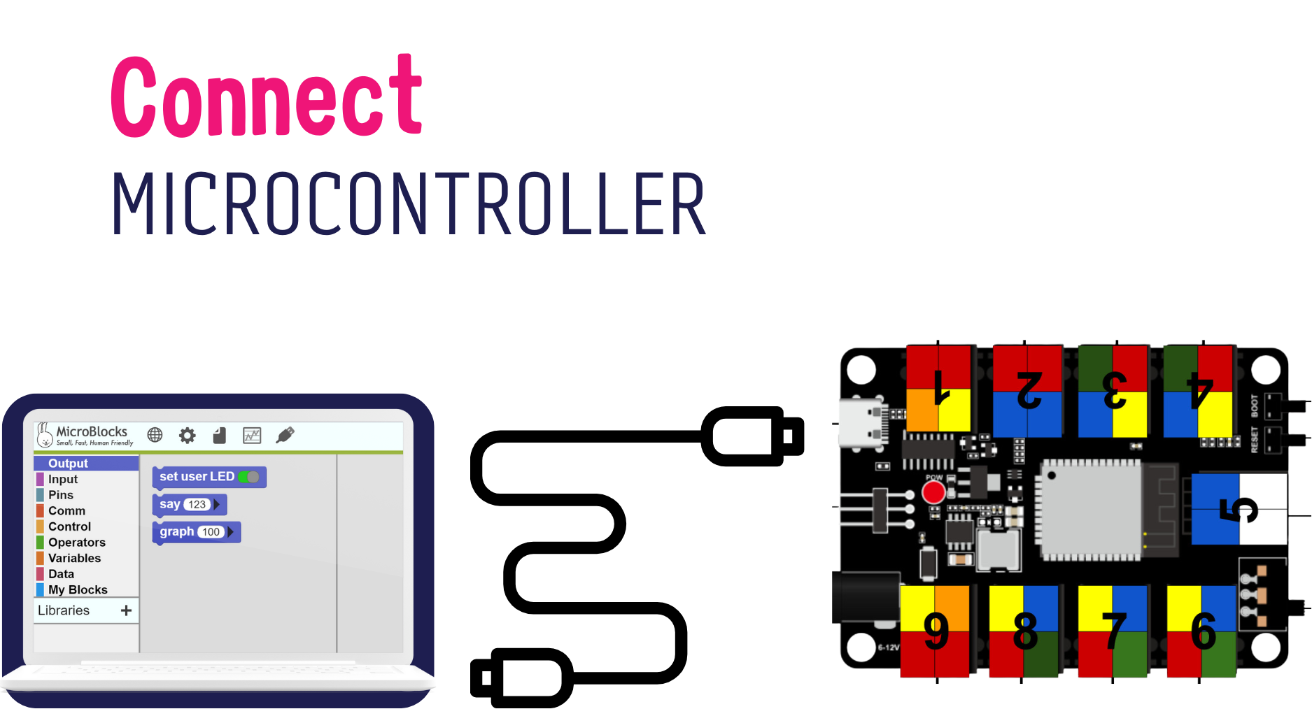
Connect the Microcontroller
[Suggested Time: 10 mins]
Learners Activity:
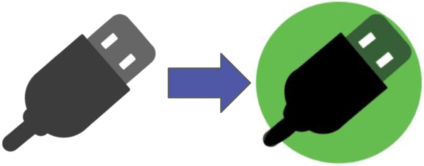
Connect the Microcontroller using USB-C Cable to the laptop, and notice what happens.
Educator Activity:
Introduce the microcontroller briefly.
Ask the learners if they saw something similar.
– What does a microcontroller do?
– What are we Using it for?
Talk about the numbered PINs on the microcontroller as it will help with the activities of this level.
No need to go in detail with the layout of the microcontroller and its possible functionalities, as that will be covered in LEVEL 3.
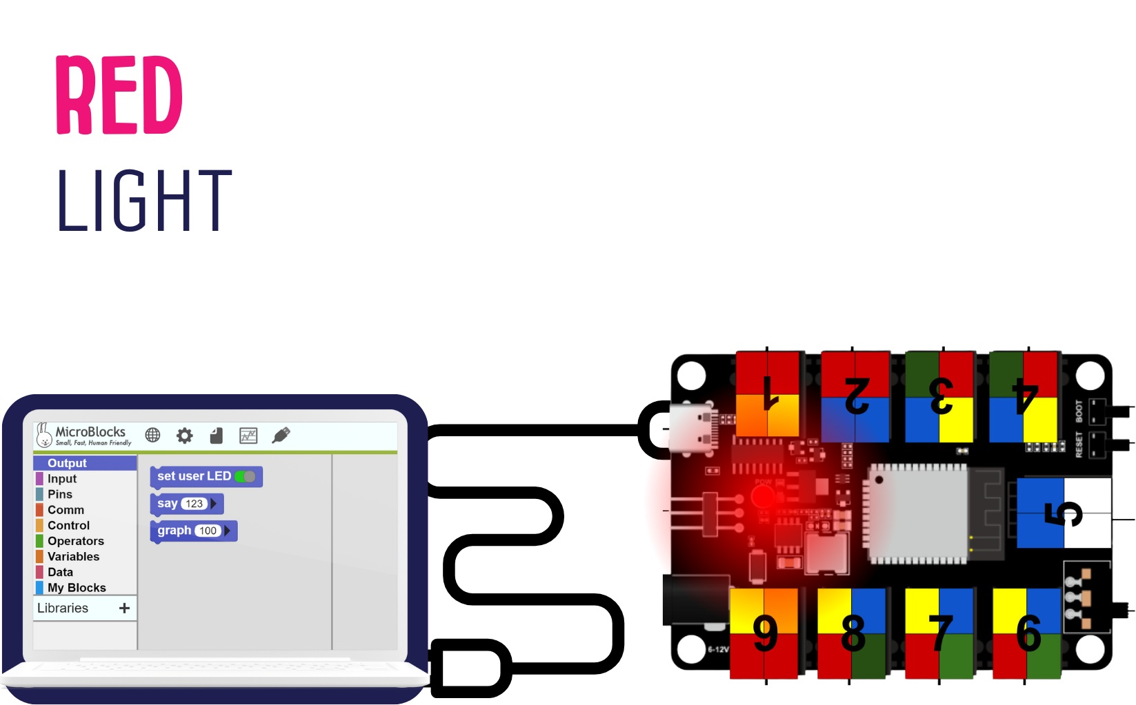
Red Light
Educator Activity:
Ask: What happened when they connected the microcontroller.
The red light in the microcontroller should light up.
Ask: What does the red light indicate?
Troubleshooting: if the light is not let up, try changing the USB-C cable or the port used in your device.
Green Light
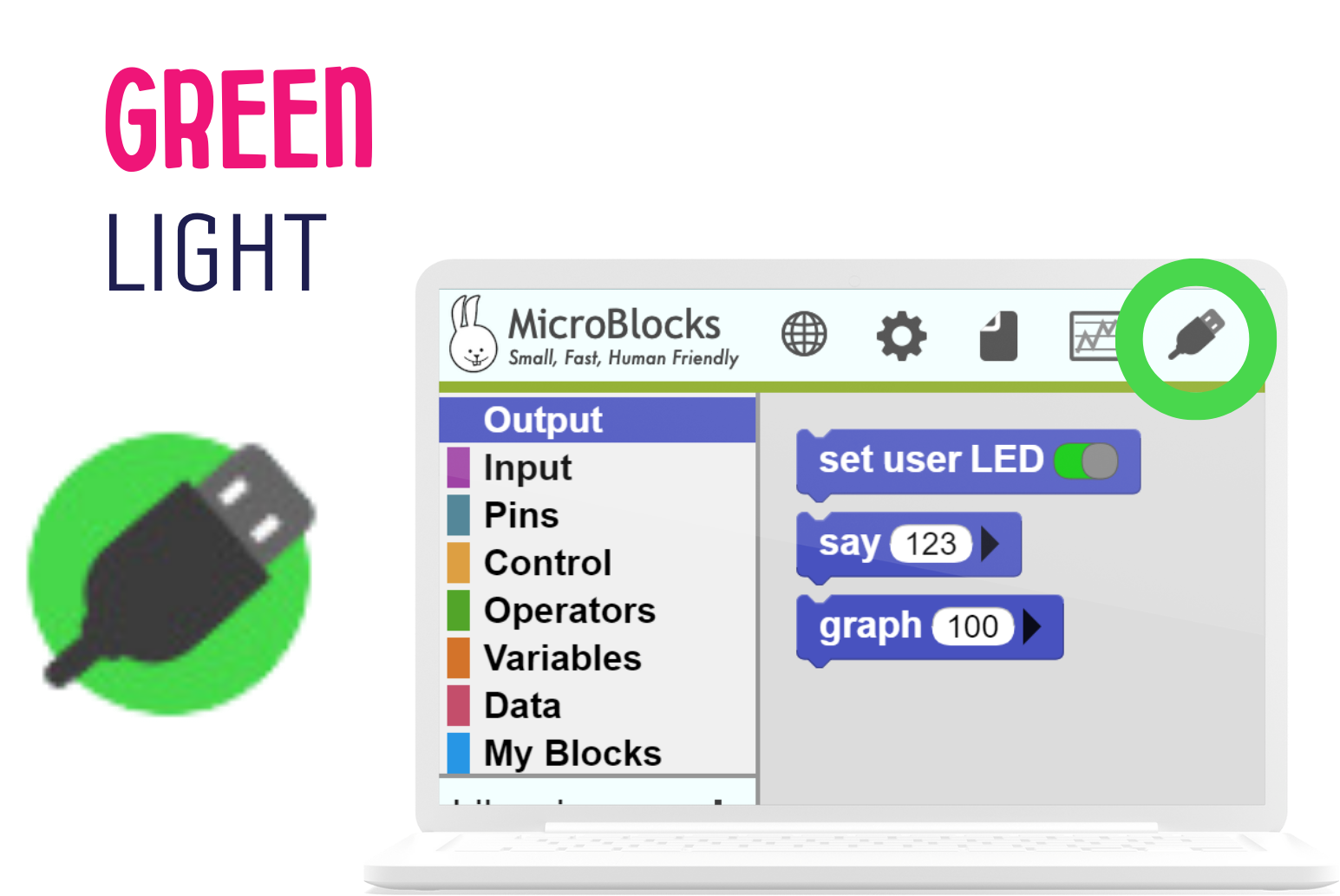
The USB Icon should be green at all times for the code to work.
If the USB icon is blinking in green, or not turning green at all, change the port in which the Microcontroller is connected to the laptop with and connect again.
Learners Activity:
Learners will try to connect the Microcontrollers to their laptops in Microblocks, to get the USB icon turn green.
Educator Activity:
Educator will be assisting learners in connecting the Microcontroller.
Discover: Let the learners discover how to turn the USB circle in Microblocks to green.
Alert: Tell the learners that they should always check that the circle is green when they are coding, as it disconnects sometimes.
Troubleshooting
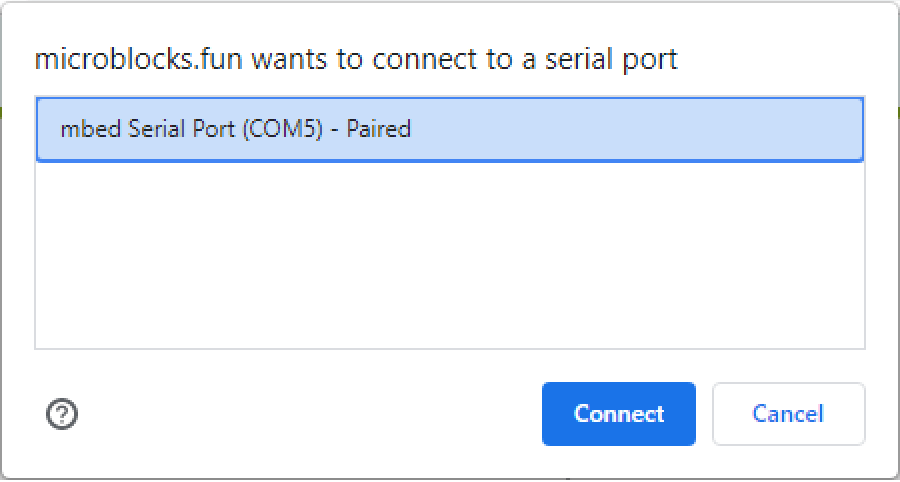
To turn the USB icon to green, click on it, then select the port in which the Microcontroller is connected to.
If the port does not show up, try refreshing the page, or restating the device.
If there is still issues with connection, follow these steps:
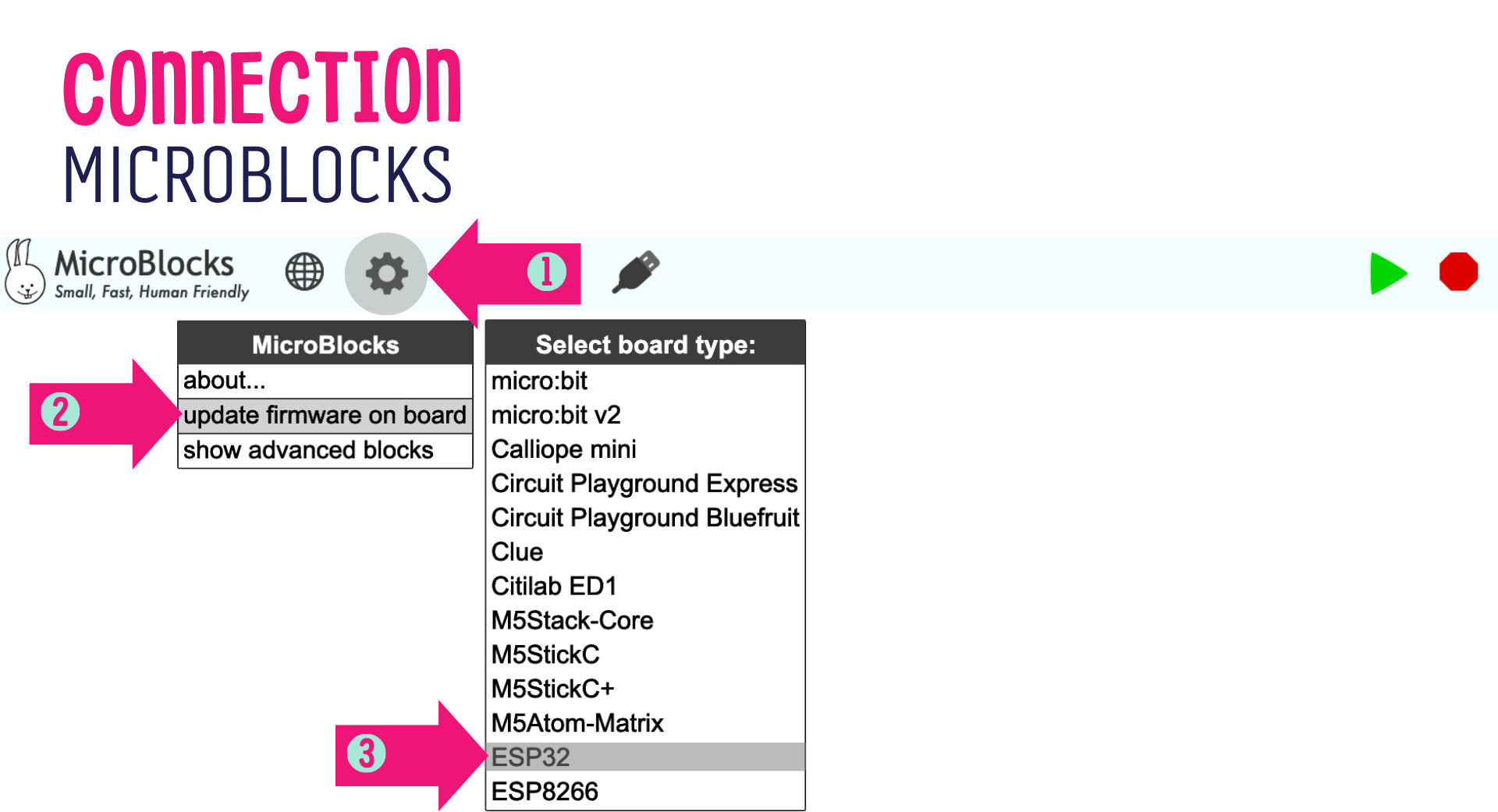
STEP 1: Click on [Gear Icon]
STEP 2: Click on [update firmware on board]
STEP 3: Click on [ESP32]
After it completes loading, you will have to connect from the USB icon again.
If there is any other issue, you can check [Microblocks.fun Get Started]
Download & Open Codes
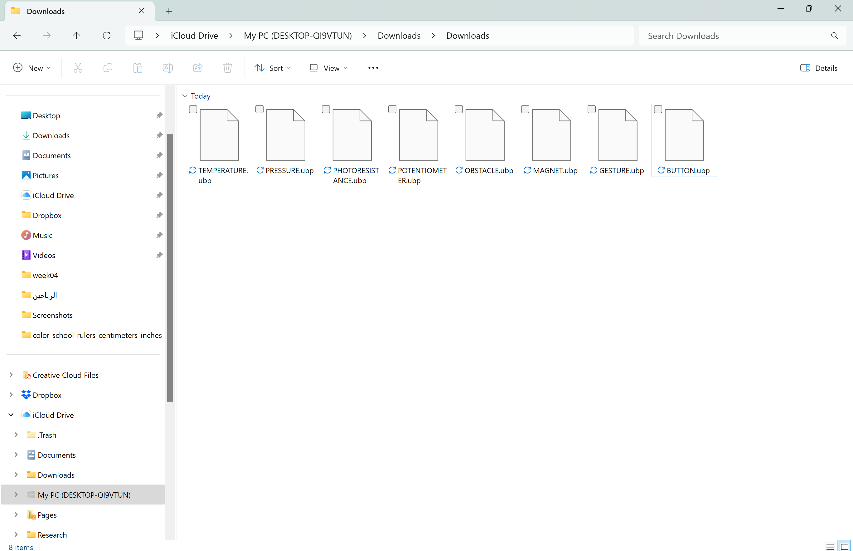
Make sure all 8 different codes are downloaded in the computer.
They will most likely be in the [Downloads] folder.
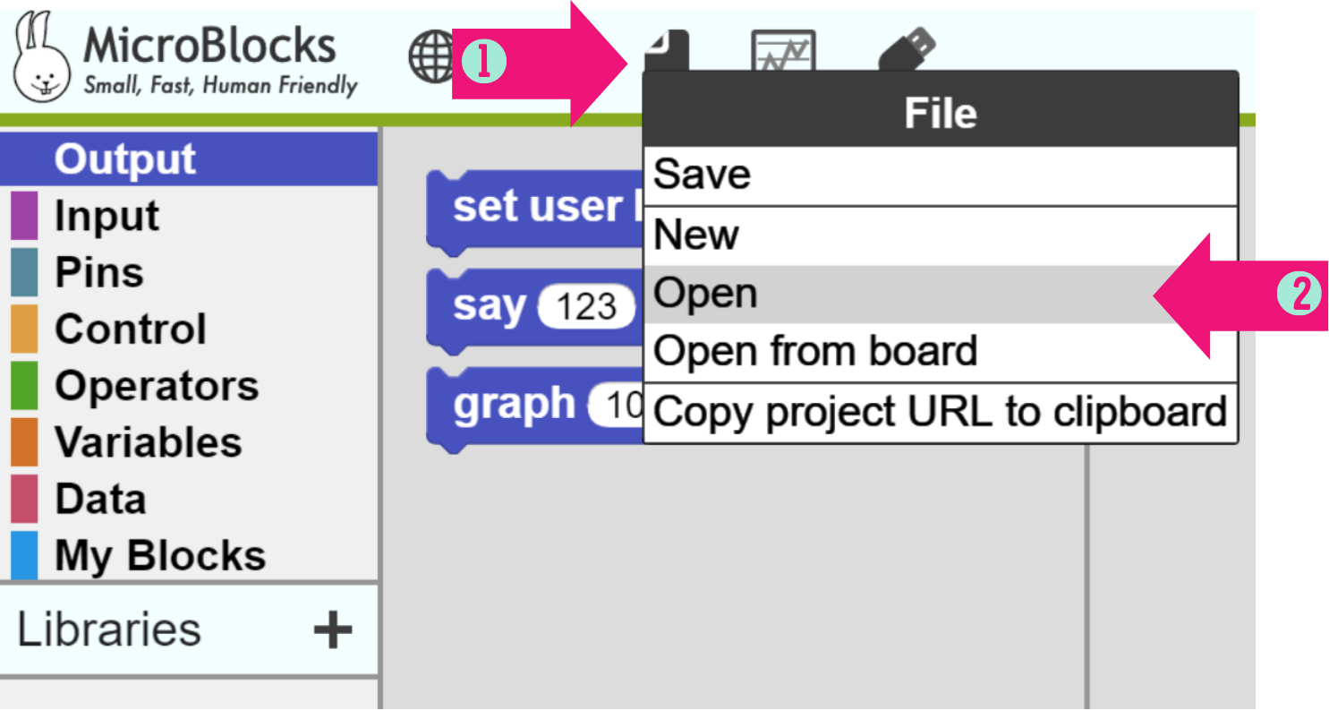
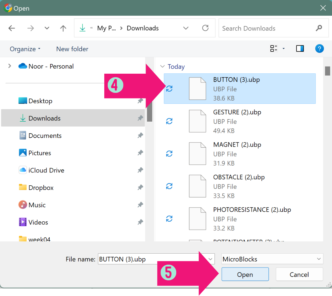
STEP 1: Click on [file]
STEP 2: Click on [Open]
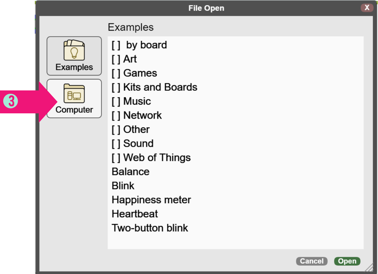
STEP 3: Click in [Computer]
STEP 4: Select the code you want to start with [codes have the same name as the tasks in the sheet]
STEP 5: Click on [Open]
Another way to open the codes is to drag and drop them in Microblocks workspace.

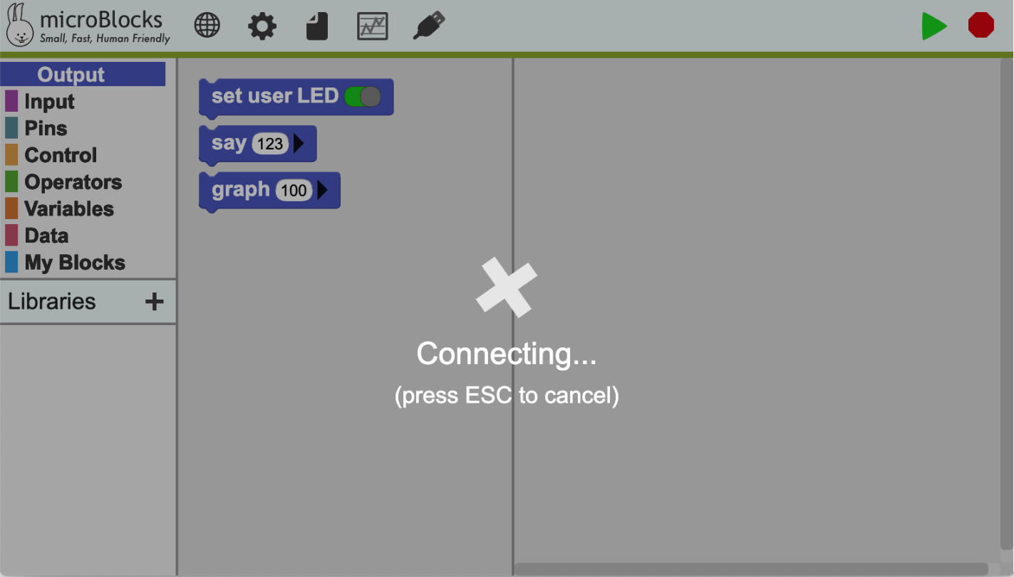
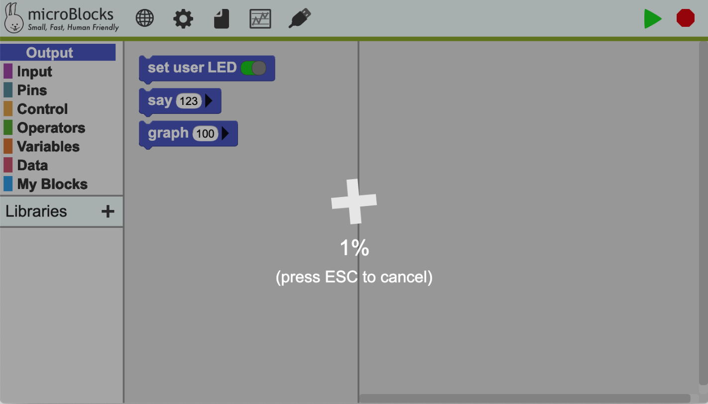
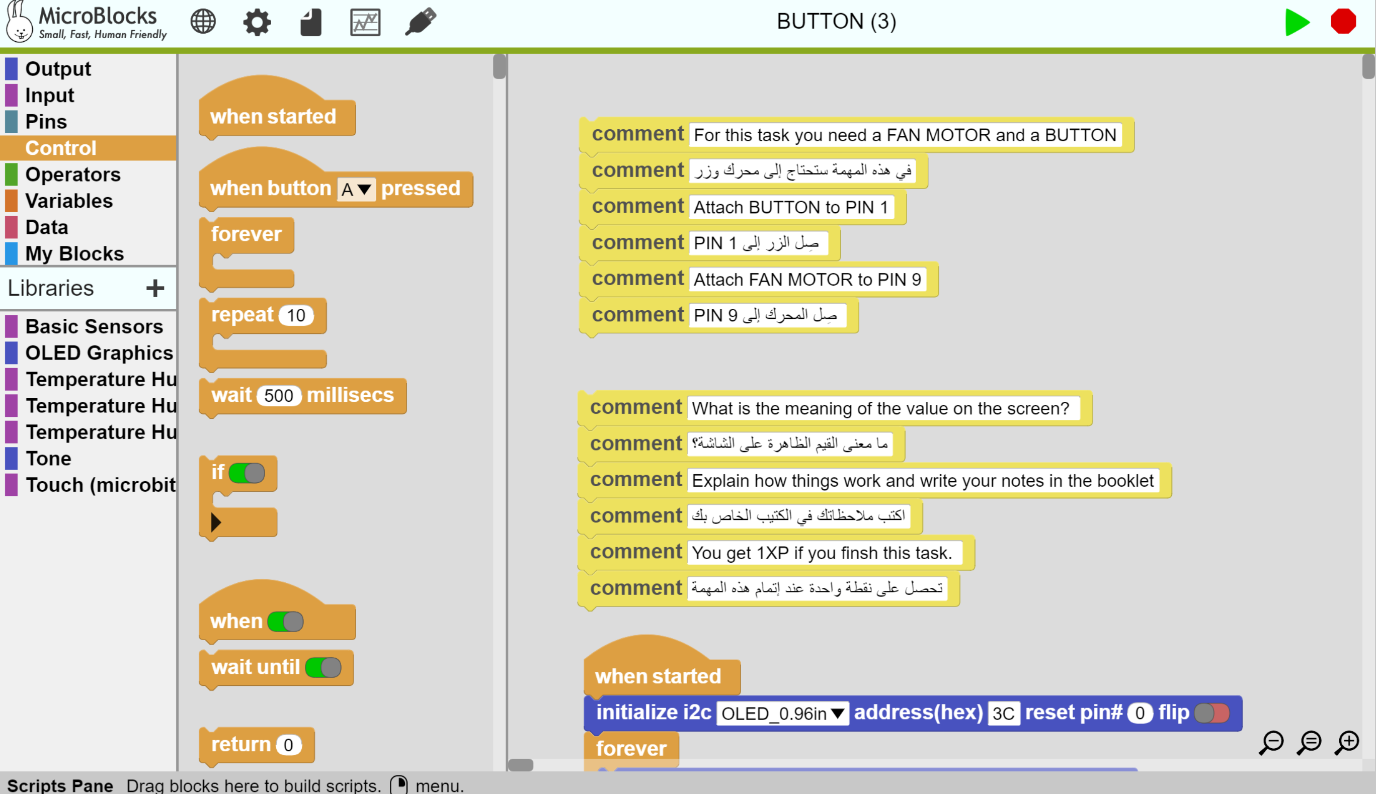
After opening the code file, the code blocks will show in the workspace, along with yellow comment blocks with instruction on how to run the code.
Click in the green start button![]() to run the code, and the red button
to run the code, and the red button ![]() to stop it.
to stop it.
If the code is running, there should be green hallow around it.
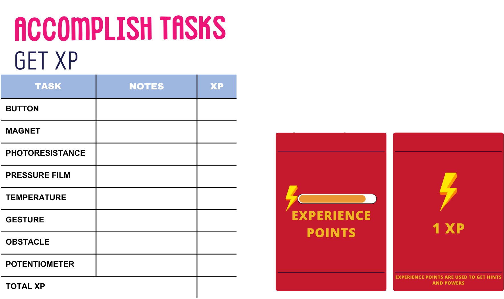
Tasks Time
[Suggested Time: 40 mins – 1 hr]
Learners Activity:
Learners now will follow instructions written in yellow comment blocks to accomplish the task.
After finishing one task, learners will ask educator to evaluate them and give them xp points if task is complete.
Learners will then follow the same steps shown previously to work one the next task.
Learners will answer questions in the comments and write their notes in SPARK Booklet page for LEVEL 1, found [here].
Educator Activity:
Educator will go around learners to check their tasks, assist in needed tasks, and give xp points.
Educator will ask learners to go to the next task if they accomplished the previous one.
Educator will keep track of tasks accomplished and manage time.
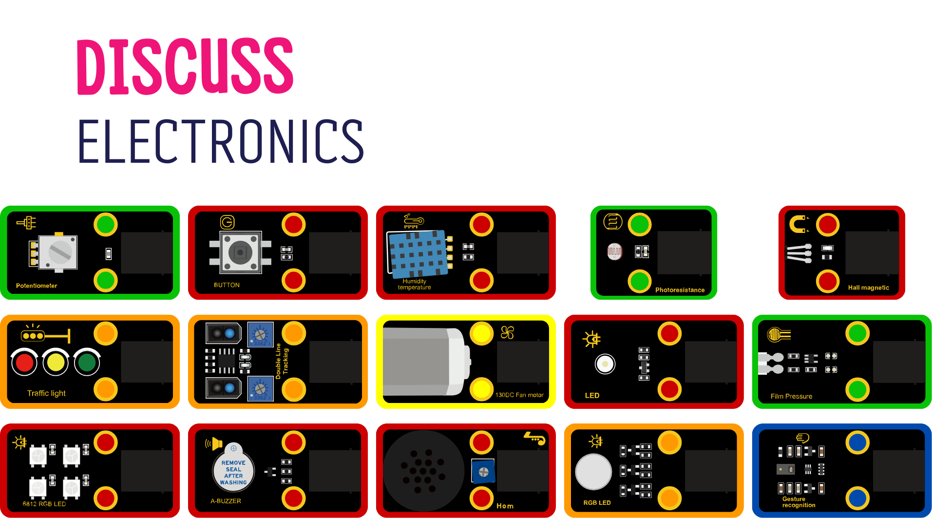
Know your Electronics
[Suggested Time: 20 mins]
Learners Activity:
Learners will discuss their notes written during accomplishing tasks.
Learners will answer educators questions regarding the electronics used.
Educator Activity:
Ask learners:
– What electronics did you try?
– What inputs did you try? What are the values they read?
– What outputs did you try? Have you tried different outputs [light/movement/sound]?
– The colors of the modules are different, what could that mean? How can they be categorized?
Different colors indicate the type of signal the module gives, Digital, Analog, PWM, I2C, or Multiple Pin Module.
Notice: Red Modules [Digital] gives readings of 0/1, while Green Modules [Analog] gives a range of values 0-1023.
Codes Explained
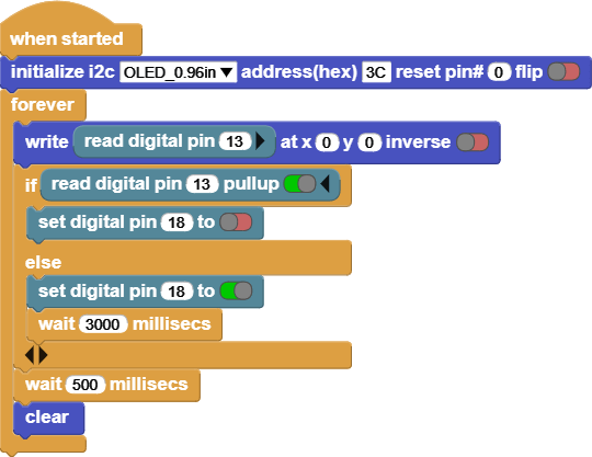
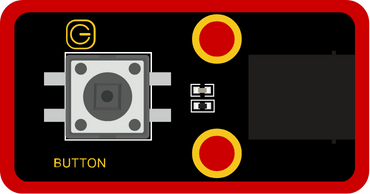
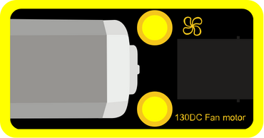
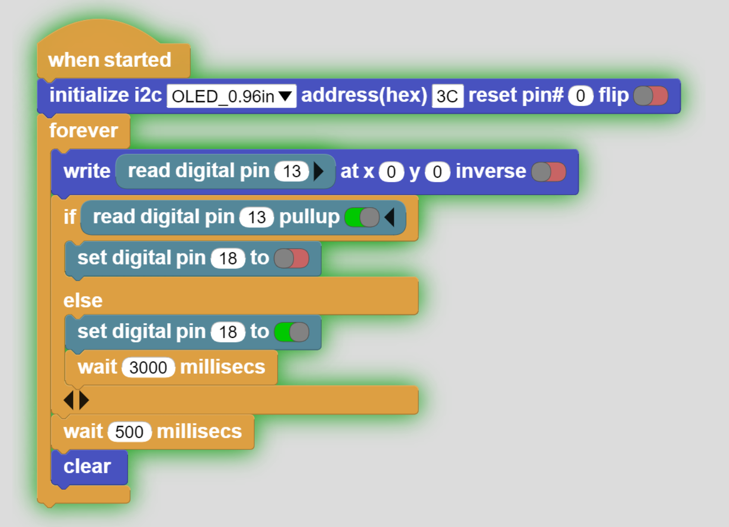
INPUT: Button
OUTPUT: 130DC Fan Motor
Click on the Button and notice the screen and the Fan Motor.
This code reads the value of the Button, and based on the value it will turn the 130DC Fan motor on or off.
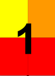
The screen shows the Button’s values, it is either [1 or 0].
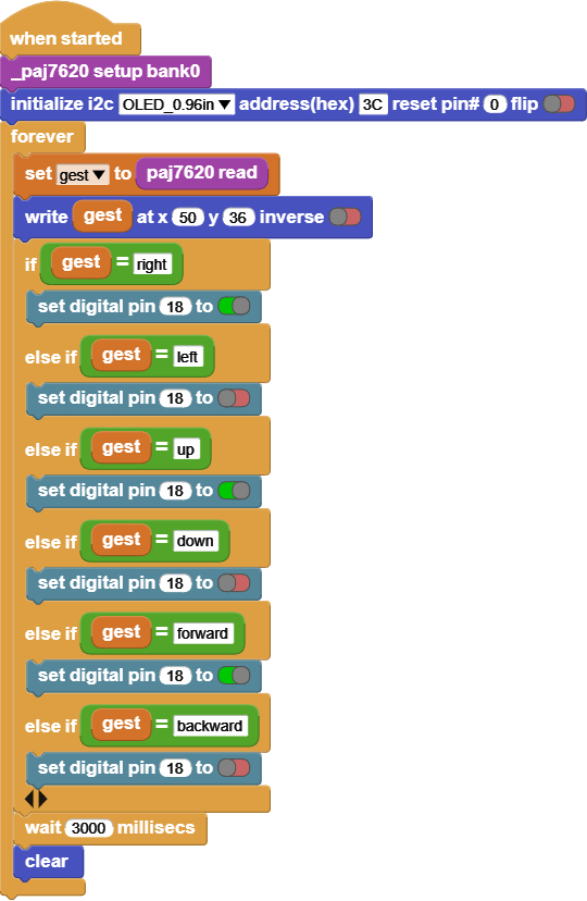
INPUT: Gesture recognition
OUTPUT: 130DC Fan Motor
Move your hand in front of the gesture recognition and notice the screen and the fan motor.
This code reads the value of the Gesture recognition, and based on the value it will turn the 130DC Fan motor on or off.
The screen shows the gesture values, it reads [right, left, up, down, forward, backward, clockwise, anticlockwise].
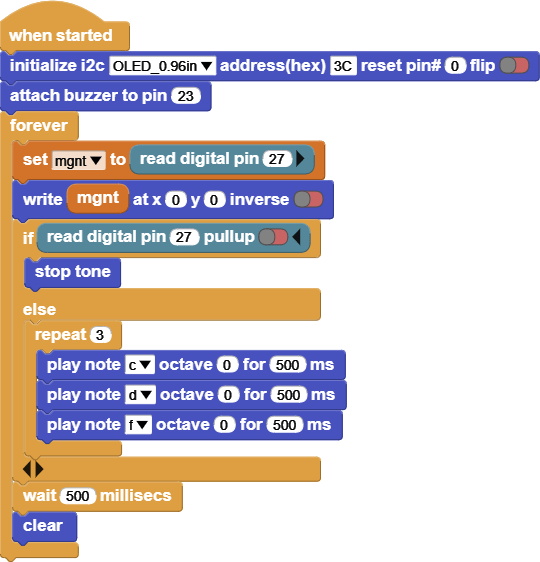
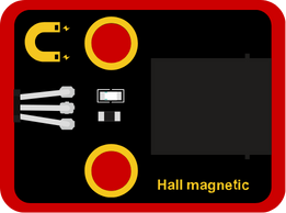
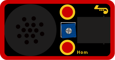
INPUT: Hall magnetic
OUTPUT: Horn
Get a magnet next to Hall magnetic, and notice the screen and the Horn.
This code reads the value of the Hall magnetic, and based on the value it will turn the Horn on or off.
The screen shows the Hall magnetic values, it reads [1 or 0].
![]()
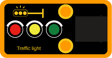
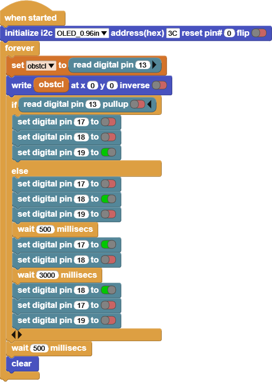
INPUT: Double Line Tracking
OUTPUT: Traffic Light
Put your hand in front of the Double Line Tracking and notice the screen and the Traffic light.
This code reads the value of the Double Line Tracking, and based on the value it will change the color of the traffic light.
The screen shows the Double Line Tracking values, it reads [1 or 0].
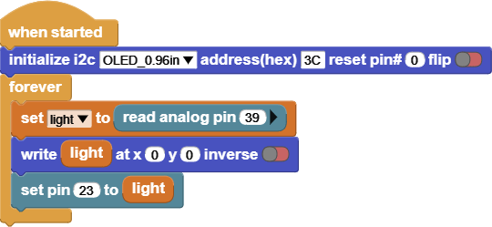
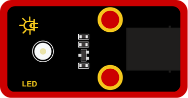
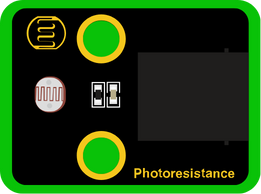
INPUT: Photoresisance
OUTPUT: LED
Try to change the lightning around the photoresistance by putting a cover on to make it dark around it, or a flash light to make it bright and notice the values on the screen and the LED.
This code reads the value of the Photoresistance, and based on the value it will change the LED brightness.
The screen shows the Photoresistance values, it reads [between 0 – 1023].
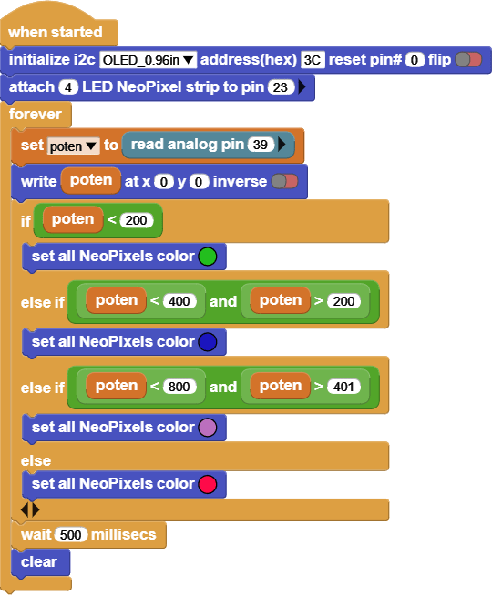
INPUT: Potentiometer
OUTPUT: 6812 RGB LED
Try rotating the potentiometer, and notice the values on the screen and the 6812 RGB LED.
This code reads the value of the Potentiometer, and based on the value it will change the 6812 RGB LED colors.
The screen shows the Potentiometer values, it reads [between 0 – 1023].
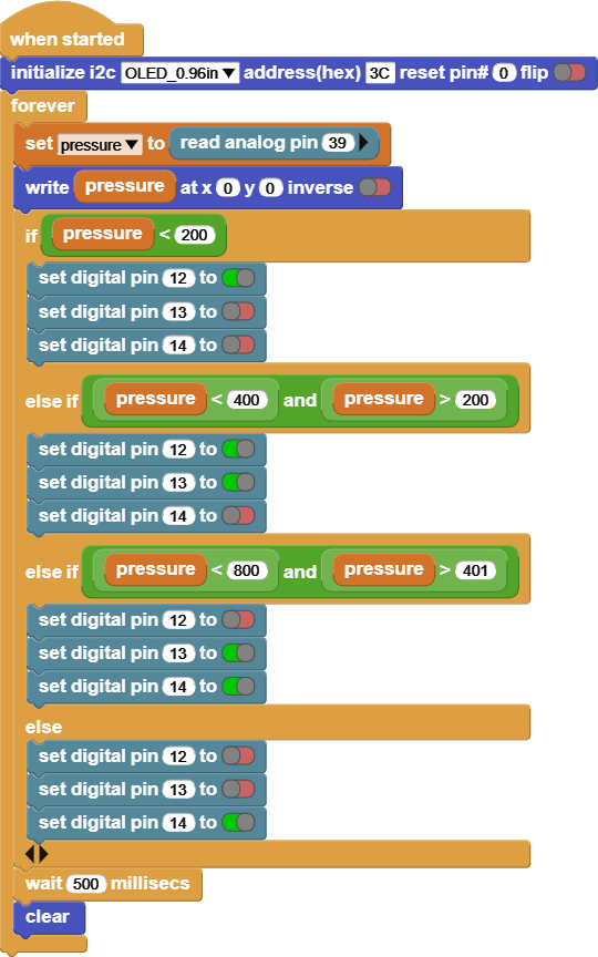
INPUT: Film Pressure
OUTPUT: RGB LED
Try pressing on the Film Pressure with different pressures and notice the screen and the RGB LED colors.
This code reads the value of the Film Pressure, and based on the value it will change the RGB LED colors.
The screen shows the Film Pressure values, it reads [between 0 – 1023].
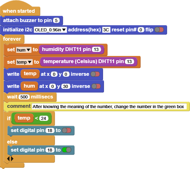
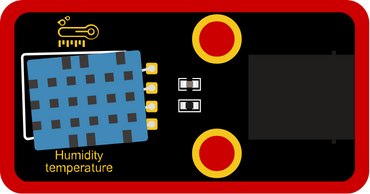
INPUT: Humidity Temperature
OUTPUT: 130DC Fan Motor
Try changing the temperature around Humidity Temperature sensor by applying hot air or cold air, and notice the screen and the Fan Motor.
This code reads the value of the Temperature, and based on the value it will turn the Fan Motor on or off.
The screen shows the Temperature and Humidity values, it reads [temperature in Celsius and percentage of humidity].


